Connecting and Attaching Elements
After elements have been added to a model, you can define connections and attachments. Sigmafine uses connections to indicate material flow in and out of elements using connectors, which show visual links between elements. Attachments associate measurements with flows and other elements like Analyzers.
The Sigmafine Element templates hold definitions for how the ports of an Element participate in connections and attachments. These rules include the following:
- The type of port – Input, Output, or Undirected.
- The maximum number of connections on a port.
- The types of elements that are allowed to connect.
- The port designated as the default.
To add a connection or an attachment to an Element that is part of a model, follow the steps below. Note that only the first step (to open the Element Connections window) is different when using System Explorer as opposed to Modeler.
Use System Explorer or Modeler to open the Element Connections window.
In the navigation pane, select Elements.
In the Elements list, click on the Model to which the connection is to be made.
Click on the Element under the Model for which you want to make a connection.
The elements details display in the right pane.
Click on the General tab, if not already selected.
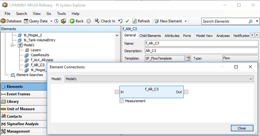
Click on Connections to open the Element Connections window (as shown in Figure 168).
In the AF Browser, click on the Model tab.
From the Element list, select the Element in the Model for which the connection is to be made.
Alternatively, you can click on the Element in the Model display on the right.
In the AF Property pane on the left, click on the General tab.
In the Find section, click the Connections link to open the Element Connections window (as shown in Figure 169).

Depending on the type of connection, click on the
 small select box for In (input), Out (output) or Measurement (measurement port) to add the corresponding Input, Output or Measurement connections to the element.
Depending on the type of connection you want to make, click on the
small select box for In (input port), Out (output port) or Measurement (measurement port) to add the corresponding Input, Output or Measurement connections to the element. Refer to Figure 168 and Figure 169 to view the selection boxes.In and Out are used to add the corresponding input and output connections, while Measure is used to add Analyzer/meter connections.
A Make Connection window opens.
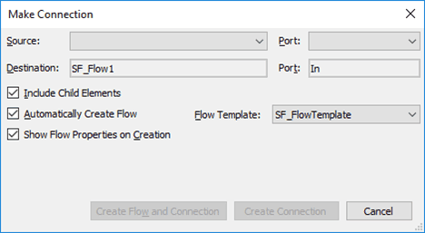
If you clicked the In or Out box to add an input port or output port connections
Click on the Source (for 'In') or Destination (for 'Out') down-arrow and make the appropriate selection.
The Port value box is automatically populated.
Check the Include Child Elements checkbox to view the child elements in the drop-down menu.
Click the appropriate button to submit the form.
If you clicked the Measurement box to add Analyzer/meter connections
Click on the Destination down-arrow to select the measurement elements.
Under Measurement, select the analyzer/meter to use.
Click the appropriate button to submit the form.
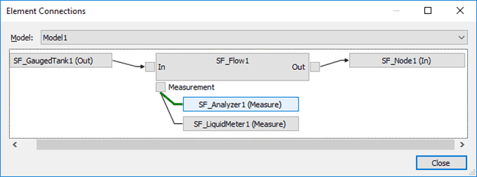
Your selections display under Measurement in the Element Connection display (as shown in Figure 171).
(Optional) Navigate to any of the other elements by clicking on it.
(Optional) To delete a connection, right-click on it and select Delete Connection from the pop-up menu.
After the you are finished with the connections, click Close to save your selections and close the Element Connections window.
If working in the Modeler, the connected elements are shown as connected in the display (see example Figure 174).
If working in the Modeler, you can verify that the connections are made by clicking and holding an element (example flow).
All the elements that are connected or attached are highlighted; the connectors are highlighted in green (see Figure 175).


